Formulas: Beveled Retaining Rings
The purpose of beveled rings, when used within their specified limits, is to assure the user that in all assemblies there will always be an axial force exerted on the retained part by the retaining ring. This concept is illustrated below:
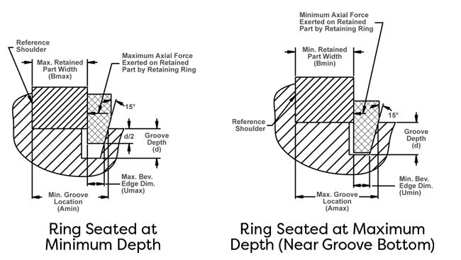
In almost all applications, the ring will seat at depth somewhere in between the limits shown. The allowable “take-up” capability of a ring is its ability to compensate for the dimensional variation of the components in an assembly. Whether a beveled ring can be used in this way depends on two factors:
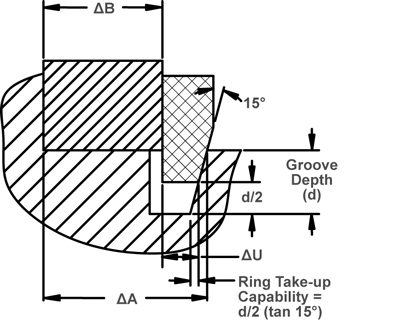
- The summation of the three relevant tolerances which determine the take-up required. As can be seen in the drawing (upper right), these parameters are the variation in retained part width (ΔB), groove location (ΔA), and ring beveled edge (ΔU). For simplicity of analysis, the groove and ring 15° angles are assumed to have no variability.
- The capability of the ring to provide take-up or compensation for the variability of the assembly components listed above. For the ring to provide sufficient take-up to compensate for the variability, and to seat within the limits d/2 to d, the following requirement must be satisfied:
Ring take-up capability [d/2 (tan 15°)] ≥ ∆A + ∆B + ∆U
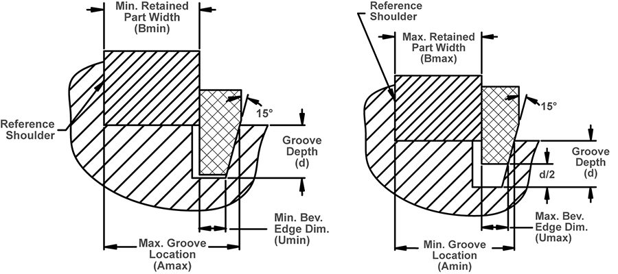
If the take-up requirement is satisfied, the groove location limits (Amin & Amax) can be calculated as follows:
Amin = Bmax + Umax + d/2 (tan 15°)
Amax = Bmin + Umin + d (tan 15°)
As an example of this technique, assume that a VHO-200 ring is used to retain a part with a width dimension of 1.000 ±.002.
The groove location limits will be as follows:
Amin = 1.002 + .045 + .072/2 (tan 15°) = 1.057
Amax = .998 + .043 + .072 (tan 15°) = 1.060
If the user’s ability to locate the groove requires less than the .003 allowable tolerance, the maximum seating depth position can be moved up the groove to provide a higher minimum axial force.
Until now, the explanation has focused on a technique which will assure that 100% of the assemblies will have the ring seated within the limits shown. If the user will accept a statistically small number of assemblies (2 out of 1000) with the ring seating slightly outside of these limits, the statistical groove location technique can be used. This will provide slightly more take-up than the technique described above. Please contact the Rotor Clip Engineering Department for information about this concept.
More than Parts. A True Partnership.
Our passion is creating the best rings, springs, and clamps. Our mission is to make your work a success. We are here for you.