Technical Considerations for the Selection of Retaining Rings
Design engineers are challenged daily to come up with economical designs that reduce weight, size, raw materials, and labor. This competitive mandate affects every facet of the design, including the fasteners needed to hold components in place. One style of non-threaded fastener that has been widely used to accomplish these goals is the retaining ring. Knowing which ring to use in a given fastening situation can greatly contribute to the overall effectiveness and economy of a design.
Just as a screw needs a correctly tapped hole, retaining rings need properly cut grooves for best performance. Both groove walls should be parallel and perpendicular to the axis of the shaft or housing. Groove depth should be held to specifications because the depth and the groove bottom radii determine the amount of support the load bearing groove wall will provide. The edge margin–which is the distance of the groove from the end of the shaft or housing–has been calculated to provide sufficient material to resist shearing even under maximum loads (See Figure 1).
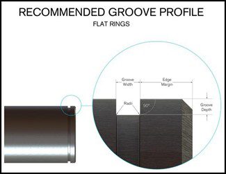
Figure 1
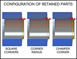
Figure 2
Since rings most often fail due to deflection, design examples are given to show how conditions affect capacity thrust. In the first assembly (See Figure 2), the part has sharp corners which provide ideal contact with the protruding portion of the ring and, therefore, the best load support. The other two–one with a radius and one with a chamfer–represent conditions that compromise thrust capacity. You will notice that the retained part contacts the ring at its outer edge. When a load is applied, it creates a lever action against the loaded groove wall. Under extreme loads, this can lead to deflection of the ring and ultimately to failure. If these conditions exist–and this should be carefully investigated before the design is completed—it may be advisable to consider using a reinforced retaining ring to ensure the integrity of the application.
For more help deciding which ring would best fit your application, Contact Us and ask for a Technical Salesman.
More than Parts. A True Partnership.
Our passion is creating the best rings, springs, and clamps. Our mission is to make your work a success. We are here for you.