Formulas: Wave Springs
It all begins with engineering, tap our decades of spring design expertise when designing wave springs into an application
Wave Spring Design
Rotor Clip engineers have designed wave springs for nearly every industry. Please use the following information as a reference, our team of experts is available to consult you on your project to see how a wave spring could save valuable space and weight in an application.
NOMENCLATURE
| T | = Thickness of Material | OD | = Outside Diameter | |
| SW | = Radial Width of Material | ID | = Inside Diameter | |
| F | = Load | Dm | = Mean Diameter* | |
| W.H. | = Work Height | B | = Deflection | |
| H | = Free Height | σ | = Operating Stress | |
| N | = Number of Turns | E | = Modules of Elasticity | |
| Z | = Number of Wave per Turn | K | = Wave Factor** |
*Mean Diameter Dm = [(OD + ID) / 2]
** Wave Factor K:
| Number of Waves per Turn [Z]: | 2.0 – 4.0 | 4.5 – 6.5 | 7.0 – 9.5 | ≥10.0 |
| Wave Factor [K]: | 3.88 | 2.90 | 2.30 | 2.13 |
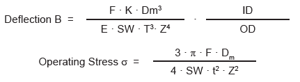
Single-Turn Wave Spring WIth Gap or Overlap
The operating stress of a single turn wave spring should never exceed the minimum tensile strength of the flat wire material. Keep deflection between 30 and 70%.
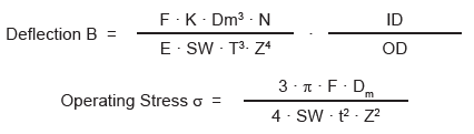
Multi-Turn Wave Spring
The operating stress of a single turn wave spring should never exceed the minimum tensile strength of the flat wire material. Keep deflection between 20 and 80%.
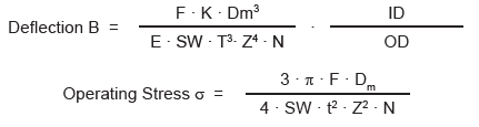
Nested Wave Wave Spring
The operating stress of a single turn wave spring should never exceed the minimum tensile strength of the flat wire material. Keep deflection between 30 and 70%.
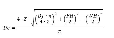
Wave Spring Diametric Expansion
The diameter of a flat wire wave spring increases when compressed in the axial direction. The following formula is an example of its maximum achievable outside diameter when compressed at the block level.
Variables:
Z = Number of Waves per turn
Df = Free (uncompressed) Diameter
Dc = Compressed Diameter
FH = Per turn Free Height
WH = Per turn Work Height (per turn compressed height)
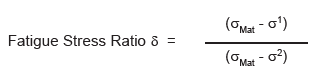
Fatigue Stress Ratio
Calculating the ratio between Work Height 1 and Work Height 2 can determine the required number of load cycles. The results are then compared to the guideline table values to figure out final number.
| δ | Fatigue Stress Ratio | σ1 | Calculated operating stress at lower work height | |
| σMat | Material tensile strength | σ² | Calculated operating stress at upper work height |
| FATIGUE GUIDELINES | |
| Fatigue Stress Ratio δ | Estimated Cycle Life |
| < 0.40 | < 30.000 |
| 0.40 – 0.49 | 30.000 – 50.000 |
| 0.50 – 0.55 | 50.000 – 75.000 |
| 0.56 – 0.60 | 75.000 – 100.000 |
| 0.61 – 0.67 | 100.000 – 200.000 |
| 0.68 – 0.70 | 200.000 – 1.000.000 |
| > 0.70 | > 1.000.000 |
More than Parts. A True Partnership.
Our passion is creating the best rings, springs, and clamps. Our mission is to make your work a success. We are here for you.