Formulas: Retaining Ring Load Capacity
Static Thrust Loads
1. ALLOWABLE THRUST LOADS – RINGS (Pr or P’r)
Maximum allowable static thrust capacities for rings normally used with grooves are listed in the data charts for each ring type. The load limits are given for rings (Pr or P’r) and grooves (Pg).
The values for Pr or P’r are applicable only when the ring is installed in a housing or on a shaft made of hardened steel where the thrust load capacity of the groove is equal to or greater than that of the ring. When the ring is seated in a groove cut in softer material, and Pg is less than Pr or P’r, Pg becomes the limiting factor in the assembly.
For maximum thrust capacity in both static and dynamic loading, the abutting face of the retained part should have a square corner. Fit of the retained part in the housing or on a shaft should allow reasonably concentric uniform loading against the ring.

When there is radial play between the retained part and the shaft or housing, such play must be treated as though the retained part had a chamfered corner. The magnitude of the chamfer should be considered equal to the play. Loading data for rings abutted by chamfered parts (P’r) as shown in the specific ring data charts must be considered. (See CORNER RADII & CHAMFERS)
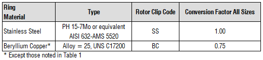
Allowable load capacities for rings (Pr) apply only to standard thickness rings made of standard materials using the shear strength values listed in Table 1. When the following special materials are used, multiply the allowable thrust load of the ring by the conversion factor shown below.
2. ALLOWABLE THRUST LOADS — GROOVES (Pg)
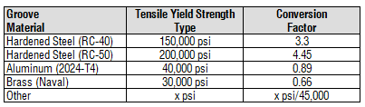
The allowable thrust loads listed in column Pg of the data charts for rings used in grooves are based upon a housing or shaft material of cold rolled steel with a tensile yield strength of 45,000 psi. In the case of Series VHO and VSH beveled rings, the values given are for minimum contact between ring and groove—i.e., engagement of the beveled edge of the ring with the beveled groove wall at a length equal to half of the groove depth (d/2).
When the following materials are used, multiply the allowable thrust load of the groove by the conversion factor shown below.
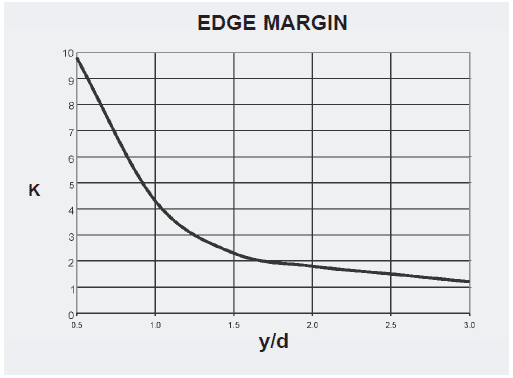
3. CALCULATING EDGE MARGIN
The distance from the groove to the end of the shaft or housing is known as edge margin. Edge margin is a calculated distance based on the relationship between the edge margin (y) and the groove depth (d). When y/d≥3, the groove will withstand the maximum thrust load as indicated in the Rotor Clip catalog specification page for that particular size and type of retaining ring.
Example: SH-50 external retaining ring installed on a cold-rolled steel shaft. The catalog specifications for this ring call; for a minimum edge margin of 0.048″ and a groove depth of 0.016.” Our formula is as follows:
y/d≥3 (0.048”/0.016″) = 3
There is sufficient edge margin for the groove to withstand the maximum thrust load of 550lbs. listed in the catalog specifications. If an application requires an edge margin less than the recommended specifications, it is necessary to calculate the thrust load (Pg) – capacity of the groove, to determine if the reduced margin is capable of handling the anticipated thrust load. The following formula applies (Note: See Correction Factors table for Gf value; Yield Strength of Groove Material for σy value; Edge Margin Graph for K1 value; Nomenclature Table for remaining catalog specifications):
Pg = (GfDsdπσy) / (K1Fs)
For this example, assume that the edge margin will only be half the listed catalog value or, y/d=1.5. The above equation is as follows:
Pg = [(1) .5 x .016 x 3.14 x 45,000] / (2.20 (2))
= 1130.4 / 4.40
= 256.9 lbs. Maximum thrust load for reduced edge margin

Finite Element Analysis shows stress gradients for a retaining rings in an application with insufficient edge margin. When loaded, the high stress region extends over the entire groove wall to the end of the shaft (or housing) and the groove wall actually distorts. Under these conditions, the ring would buckle, possibly leading to catastrophic failure.

4. THICKNESS OF HOUSINGS AND HOLLOW SHAFTS
The allowable load of a part in which a retaining ring groove is cut depends upon the ultimate tensile strength and tensile yield strength of the material used, and on the bearing area of the ring against the groove wall. For internal rings used in bores and housings — and external rings assembled on hollow shafts — wall thickness dimension w, illustrated below, can be calculated from the formulas:
For internal rings:

For external rings:

where:
| Ds | = Shaft or housing dia. (in.) |
| Dg | = Groove dia. (in.) |
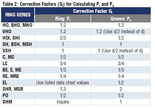
| Gf | = Correction Factor [See Table 2] |
| d | = Groove depth (in.) |
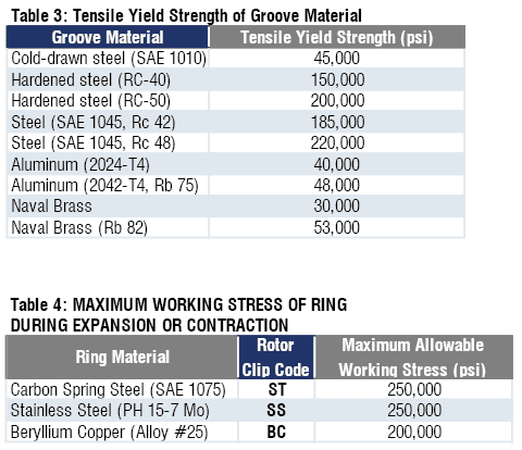
| σy | = Tensile yield strength of groove material (psi) [See Table 3] |
| σu | = Ultimate tensile strength of groove material (psi) |
These formulas provide for a wall thickness that is safe for allowable groove thrust loads (Pg) calculated with the formula at the right. If substantially lighter loads will be encountered and a thinner wall is desired, actual tests are recommended.
5. LOAD LIMIT FORMULAS
Formulas for determining ring and groove load limits — with sample calculations for Series HO internal rings and Series SH external rings — are given below. The loads are calculated for retained parts having sharp corners. Correction factors (Gf) for calculating Pr and Pg are given in Table 2. The correction factors are based upon the load characteristics of the rings.
In these examples assume y ≥3d. Therefore, K = 1 and is not shown in formulas for Pg.
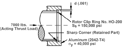
Internal Ring (Example: Series HO-200)
ALLOWABLE THRUST LOAD — RING (Pr in lbs.)
Pr = (GfDhTπSs) / Fs
where:
| Gf | = Conversion Factor [See Table 2] |
| Dh | = Housing dia. (in.) |
| T | = Ring thickness (in.) |
| Ss | = Shear Strength of ring material (psi) [See Table 1] |
| Fs | = Safety factor |
| Pr | = ((1.2) 2.000 (.062) π 150,000) / 4 |
| = 17,500 lbs. > 7000 lbs. |
ALLOWABLE THRUST LOAD — GROOVE (Pg in lbs.)
Pg = (GfDhdπσy) / Fs
where:
| Gf | = Correction Factor [See Table 2] |
| Dh | = Housing dia. (in.) |
| d | = Groove depth (in.) |
| σy | = Tensile yield strength of groove material (psi). [See Table 3] |
| Fs | = Safety factor |
| Pg | = ( (1.2) 2.000 (.061) π 40, 000 ) / 2 |
| = 9200 lbs. > 7000 lbs. |

External Ring (Example: Series SH-100)
ALLOWABLE THRUST LOAD — RING (Pr in lbs.)
Pr = (Gf DsT π Ss) / Fs
where:
| Gf | = Conversion Factor [See Table 2] |
| Ds | = Shaft dia. (in.) |
| T | = Ring thickness (in.) |
| Ss | = Shear Strength of ring material (psi) [See Table 3] |
| Fs | = Safety factor |
| Pr | = ((1) 1.000 (.042) π 150,000 ) / 4 |
| = 4950 lbs. > 2000 lbs |
ALLOWABLE THRUST LOAD — GROOVE (Pg in lbs.)
Pg = Gf Ds d π σy / Fs
where:
| Gf | = Conversion Factor [See Table 2] |
| Ds | = Shaft dia. (in.) |
| d | = Groove depth (in.) |
| σy | = Tensile yield strength of groove material (psi). [See Table 3] |
| Fs | = Safety factor |
| Pg | = (1) 1.000 (.030) π 45,000 |
| = 2100 lbs. > 2000 lbs |
Dynamic Thrust Loads
Dynamic conditions most often encountered in retaining ring assemblies include sudden loading, impact, vibration, and relative rotation. Very often the loading pattern is cyclical in nature and may induce fatigue in the assembly. Where dynamic loads are likely to exist, it is necessary that actual tests of such applications be made by the ring user to insure proper functioning of the assembly. The following formulas are given for calculating the ring and or groove thrust load capacity for various conditions.
1. SUDDEN LOADING
This can occur when a surge in thrust load is transmitted to a ring installed in a tight assembly, without play between the retained part and the ring. Sudden loads of this nature should not exceed, at their maximum, 50% of the allowable static thrust load (Pr or Pg, whichever is lower).
2. IMPACT LOADING
To calculate the safe impact load capacity of the ring (Ir), the following formula should be used:
Ir = (Pr t) / 2
where:
| Ir | = Allowable impact load (in. lbs.) |
| Pr | = Allowable thrust load of ring (lbs.) |
| t | = Ring thickness (in.) |
The formula for calculating the safe impact load capacity of the groove (Ig) is:
Ig = (Pgd) / 2
where:
| Ig | = Allowable impact load (in. lbs.) |
| Pg | = Allowable thrust load of groove (lbs.) |
| d | = Nominal groove depth (in.) |
• Internal Ring (Example: Series H0-200)

FOR THE RING:
| Ir | = (Prt) / 2 |
| = (17,500 (.062)) / 2 | |
| = 540 in. lbs. > 200 in. lbs. |
FOR THE GROOVE:
| Ig | = (Pgd) / 2 |
| = (10,400 (.061)) / 2 | |
| = 320 in. lbs. > 200 in. lbs. |
3. VIBRATION LOADING
It is possible to calculate the approximate vibration load capacity of a ring and groove if there is a tight fit between the ring and the abutting retained part. (If there is space between the ring and the part, the load capacity must be calculated as impact.)
The formula for calculating the vibration load capacity of the ring is: wa ≤ 540 Pr
where:
| w | = Weight of retained parts (lbs.) |
| a | = Acceleration of parts (in./sec.2) |
| Pr | = Allowable thrust load of ring (lbs.) |
To calculate the vibration load capacity of the groove, the formula is: wa ≤ 400 Pg
where:
| w | = Weight of retained parts (lbs.) |
| a | = Acceleration of parts (in./sec.2) |
| Pg | = Allowable thrust load of groove (lbs.) |
Harmonic oscillation for both ring and groove may be calculated with the following formula: a is approx. = 40 pf2
where:
| a | = Acceleration of parts (in./sec.2) |
| p | = Amplitude (in.) |
| f | = Frequency (cycles/sec.) |
• Sample Calculation (Example: Series SH-200)
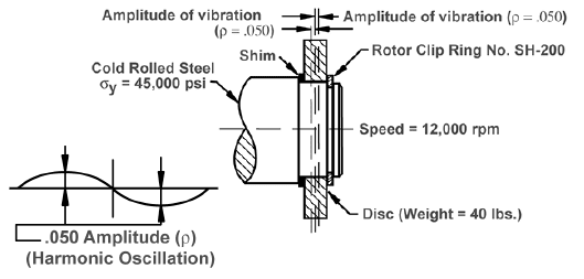
| FOR THE RING: wa ≤ 540 Pr | |
| For harmonic oscillation: | |
| a | ≈ 40 pf2 approx. |
| f | = 12,000/60 = 200 |
| a | ≈ 40 (.050) 2002 = 80,000 in./sec.2 |
| wa | = (40) (80,000) = 3.2 x 10⁶ |
| 540 Pr | = (540) (14,600) = 7.9 X 10⁶ |
| ∴ wa | < 540Pr and ring is safe |
| FOR THE GROOVE: wa ≤ 400 Pg | |
| wa | = 3.2 x 10⁶ |
| 400 Pg | = (400) (8050) = 3.22 X 10⁶ |
| ∴ wa | < 400 Pg and groove strength is adequate |
Corner Radii and Chamfers – Rmax and Chmax
All of the formulas above and the values for Pr given in the data charts for each ring type are calculated for assemblies in which the retained parts have square corners. If the abutting face of the retained part has a corner radius or chamfer, the assembly’s thrust load capacity will be lower. A Series HO-100 ring which abuts a square-cornered part, for example, has a static thrust capacity of 5,950 lbs. The same ring, seated next to a part having the maximum allowable corner radius or chamfer, has an allowable load of 1,650 lbs.
Maximum allowable corner radii and chamfers for each ring size are listed in the charts with corresponding static thrust capacities. If these thrust capacities are not sufficient for the assembly, a rigid square-cornered flat washer should be inserted between the part and the ring. The thrust capacity of the assembly will then be approximately the same as if a square-cornered retained part had been used.
When the actual corner radius or chamfer is less than the listed maximum, the allowable thrust load of the assembly increases proportionately in accordance with the following formulas:
| P”r= (P’r Rmax. ) / R | (for radius) |
| P”r = (P’r Chmax.) / Ch | (for chamfer) |
where:
| P”r | = Allowable assembly load when corner radius or chamfer is less than listed maximum |
| P’r | = Listed allowable assembly load with maximum corner radius or chamfer |
| Rmax. | = Listed maximum allowable corner radius |
| R | = Actual corner radius |
| Chmax. | = Listed maximum allowable chamfer |
| Ch | = Actual chamfer |
• Sample Calculation (Example: Series SH-125)

ALLOWABLE THRUST LOAD — RING (P”r in lbs.)
| P”r | = P’r (Chmax. / Ch) = ((1950) (.041)) / .025 |
| P”r | = 3200 lbs. > 3000 lbs. |
ALLOWABLE THRUST LOAD — GROOVE (Pg in lbs.)
| Pg | = GfDsdπσy / Fs |
| Pg | ((1)1.250(.037) π (45,000)) / 2 |
| Pg | = 3270 lbs. > 3000 lbs. |
NOTE: If the allowable thrust load capacity of the ring (Pr) or the groove (Pg) is less than P”r, Pr or Pg — whichever is lower — becomes the limiting factor in the assembly.
ELASTIC DEFORMATION WITH CORNER RADII OR CHAMFERS
Elastic deformation of an assembly (retained part, retaining ring and groove wall) where the retained part has a corner radius or chamfer can be calculated with the following formulas:
| δ = (T (.01) Ds (R + t/4 )) / ((P”r) t) | (for radius) |
| δ = (T (.01) Ds (Ch + t/4 )) / ((P”r) t) | (for chamfer) |
where:
| δ | = Deflection (in.) |
| T | = Acting thrust load (lbs.) |
| Ds | = Shaft or housing dia. (in.) |
| R | = Actual radius (in.) |
| Ch | = Actual chamfer (in.) |
| t | = Ring thickness (in.) |
| P”r | = Allowable thrust load of ring when actual corner radius or chamfer is less than listed maximum (lbs.) |
NOTE: R and Ch cannot exceed the values for Rmax and Chmax listed in the data charts for the individual ring types.
• Sample Calculation (Example: Series SH-125)
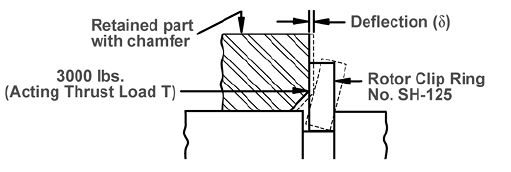
| δ | = (T(.01) Ds (Ch + t/4)) / ((P”r) t) |
| δ | = ((3000) (.01) (1.250) (.025 + .0125)) / ((3200)(.050)) |
| δ | ≈ .0087 in. |
Relative Rotation
When a retained part rotates relative to and exerts thrust on the ring, frictional forces act on the ring body. Relative rotation can reduce substantially the thrust capacity of the assembly. The use of a keyed washer or other non-rotating device between ring and retained part to eliminate relative rotation should be considered.
To prevent the rings from being “walked out” or otherwise unseated from the groove, maximum allowable rotating thrust loads may be calculated from the following formula:
Prr ≤ (s t E2) / (µ18Ds)
where:
| Prr | = Allowable thrust load exerted by adjacent part (lbs.) |
| s | = Maximum working stress of ring during expansion or contraction [See Table 4, below] |
| t | = Ring thickness (in.) |
| E | = Largest section of ring (in.) |
| µ | = Coefficient of friction between ring and retained part or groove whichever is higher (consult appropriate references) |
| Ds | = Shaft or housing dia. (in.) |
• Sample Calculation (Example: Series SH-150)

| Prr | ≤ (s t E2) / (µ18Ds) |
| Prr | ≤ ((250,000) (.050) (.1682)) / ((.2) (18) (1.500)) |
| Prr | = 65 lbs. max. |
NOTE: Relative rotation applies to the following rings made of standard materials when used in grooves: Series HO, BHO, VHO, HOI, SH, BSH, VSH, C,SHI, BE, E, RE, SHR, PO, SHF and SHM. Series LC and EL are not affected.
Deflection
Permanent deflection of ring assemblies (retained part, retaining ring and groove wall), permitting movement of the retained parts, is negligible when loads do not exceed the governing allowable thrust load (static, impact, vibration, etc. — whichever is present).
Elastic deformation, which is a temporary displacement of the retained part under load, can be calculated by the following formula:
δ = T / Ed
where:
| δ | = Deflection (in.) |
| T | = Acting load (lbs.) |
| E | = Modulus of elasticity of groove material |
| D | = Groove depth (in.) |
• Sample Calculation (Example: Series SH-100)
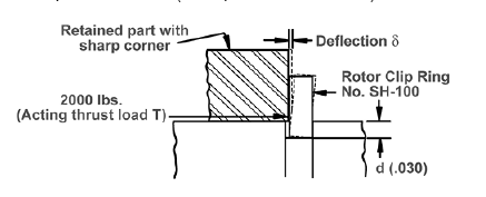
| δ | = T / (E d) |
| δ | = 2000 / ((3×10⁷)(.030)) |
| δ | = .0022” |
More than Parts. A True Partnership.
Our passion is creating the best rings, springs, and clamps. Our mission is to make your work a success. We are here for you.