


BSE-18
Looking for a specific material or finish? View complete part numbers and request a quote below.

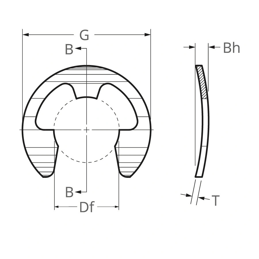
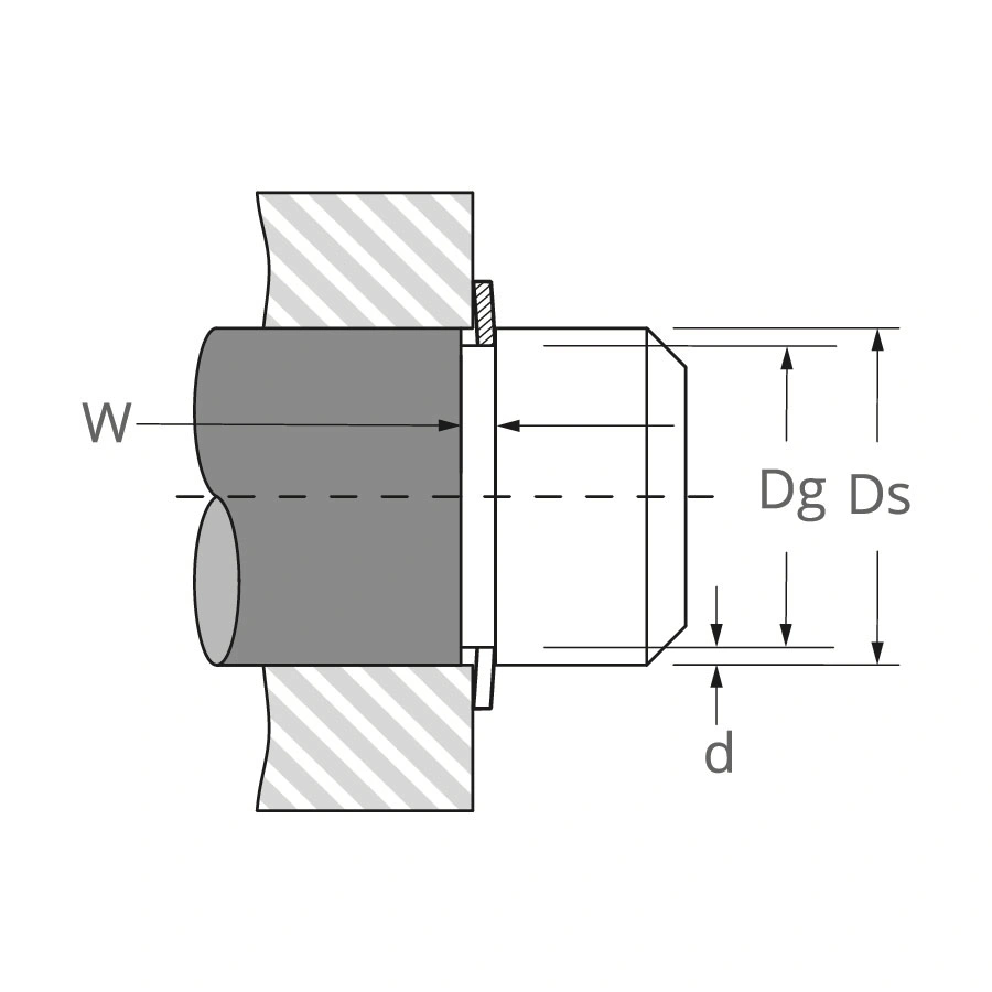
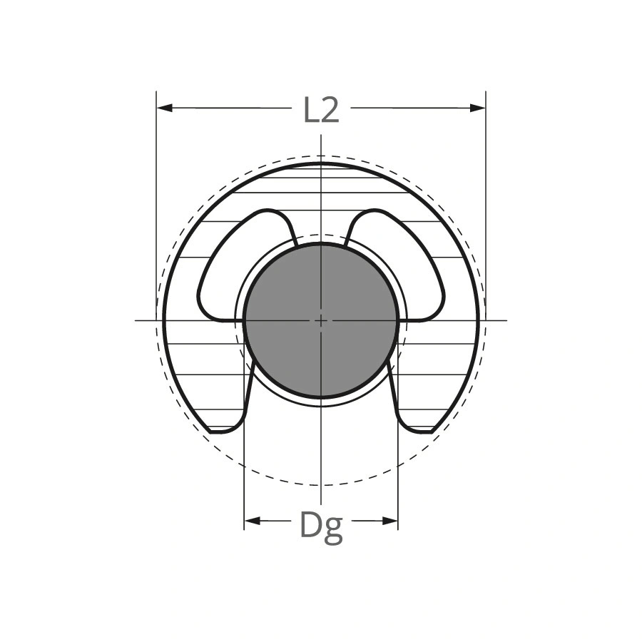
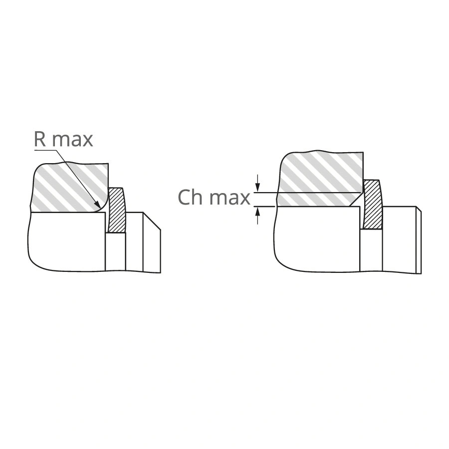
Specifications
Part Data
- Housing or Shaft Shaft
- Axial or Radial Radial
- Shaft Diameter Ds 0.188 inches
- Ds mm 4.800 mm
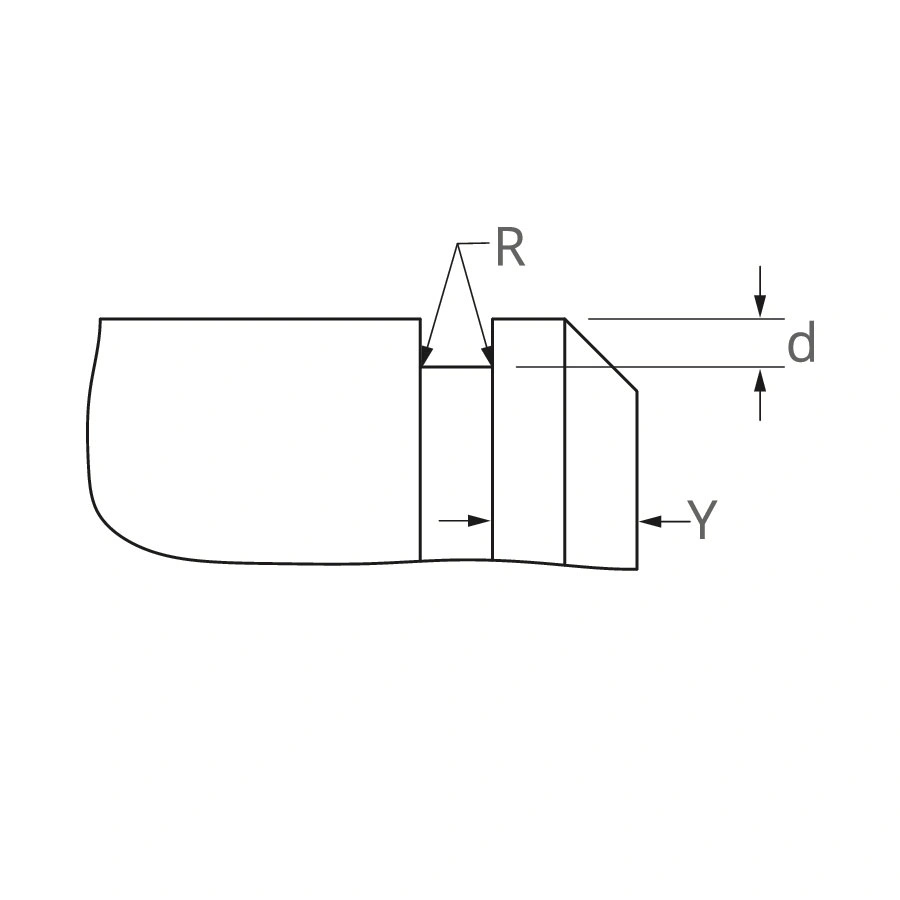
- Groove Diameter Dg 0.125 - 0.127 - inches
- Groove Width W 0.035 - 0.038 - inches
- Groove Depth D 0.031 inches
- Free Diameter Df 0.119 - 0.123 - inches
- Thickness T *** 0.013 - 0.017 - inches
- Bow Height Bh 0.038 - 0.048 - inches
- Outside Diameter G 0.375 inches
- Clearance Dia. Installed In Groove L2 0.390 inches
- Weight Per 1000 Pcs. 0.270 lbs.
- Edge Margin Y Min. 0.062 inches
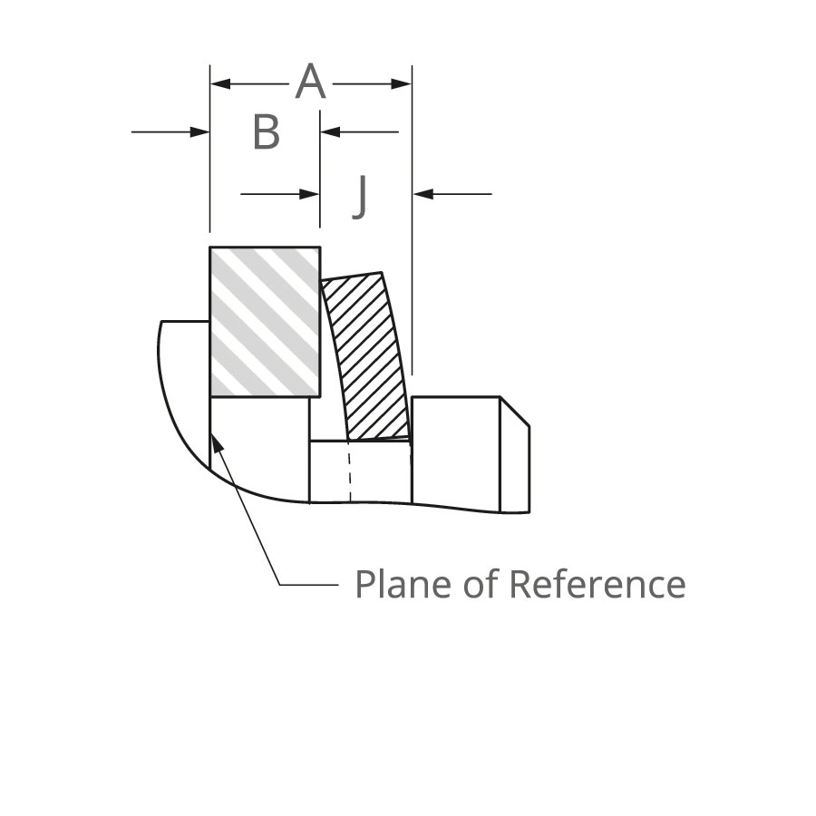
- Outer Groove Wall To Face Of Retained Part J Max 0.034 inches
- Outer Groove Wall To Face Of Retained Part J Min 0.026 inches
- Hardness ST 84.500 - 87.000 - HR15N
- Hardness SS 82.500 - 86.000 - HR15N
- Hardness BC 77.000 - 82.000 - HR15N
- Interchange Waldes Truarc X5131 18
- Interchange IRR 1001 X18
- Interchange Anderton N1504 X018
- Interchange Mil Or Aero MS16634C X18
- Interchange Din
Performance Data
- Thrust Load Ring Safety Factor Of 3 Pr 102 lbs.
- Thrust Ld. (lbs.) Groove Safety Factor Of 2 Pg 135 lbs.
- R.P.M. Limits Standard Material RPM 30,000.000
- Resilient Take-Up Of Tolerances A & B 0.008 inches
- Force Needed To Flatten Rings 16.000 lbs.
Tool Data
- End-Play Ring Applicator A-557
Product SKUs
Product SKUs listed may not include all available options. If you don't see what you're looking for, or need help selecting the right part, please contact us.
| Item SKU | Style | Material | Finish | Quote |
|---|---|---|---|---|
| BSE-18SS | Bowed Radially Assembled External/Shaft | PH 15-7 Stainless Steel | None/Self Finish | Quote |
| BSE-18ST PD | Bowed Radially Assembled External/Shaft | Carbon Steel SAE 1070-1090 | Phosphate & Oil | Quote |
| BSE-18ST ZD | Bowed Radially Assembled External/Shaft | Carbon Steel SAE 1070-1090 | Zinc Dichromate | Quote |
| BSE-18ST ZF | Bowed Radially Assembled External/Shaft | Carbon Steel SAE 1070-1090 | Zinc Flash | Quote |
Materials and Finishes
Materials
- Carbon Steel (SAE 1060-1090)
- Stainless Steel (PH15-7 Mo, PH17-7)
- Beryllium Copper
- Special Material Grades
Finishes
***For plated rings, add .002" (.05 mm) to the listed maximum thickness.
- PA - Phosphate, Carbon Steel
- PD - Phosphate and Oil, Carbon Steel
- PAL - Phosphate with Sealer, Carbon Steel
- HPD - Heavy Phosphate and Oil, Carbon Steel
- ZF - Zinc Bright, Carbon Steel
- ZDL - Zinc Dichromate with Sealer, Carbon Steel
- HZDL - Heavy Zinc Dichromate with Sealer, Carbon Steel
- Z3X - Trivalent Chromate over Zinc, Carbon Steel
- ZFF - Zinc Flash, Carbon Steel
- CF - Copper Flash, Carbon Steel
- ZD - Zinc Dichromate, Carbon Steel
Documentation
Description
Radially Assembled, External Bowed E. Compensating for accumulated tolerances is what a BE Bowed retaining ring is designed to do on a shaft. Once snapped into the groove, bowed rings exert a force or a preload on the retained parts for the range specifie
More than Parts. A True Partnership.
Our passion is creating the best rings, springs, and clamps. Our mission is to make your work a success. We are here for you.